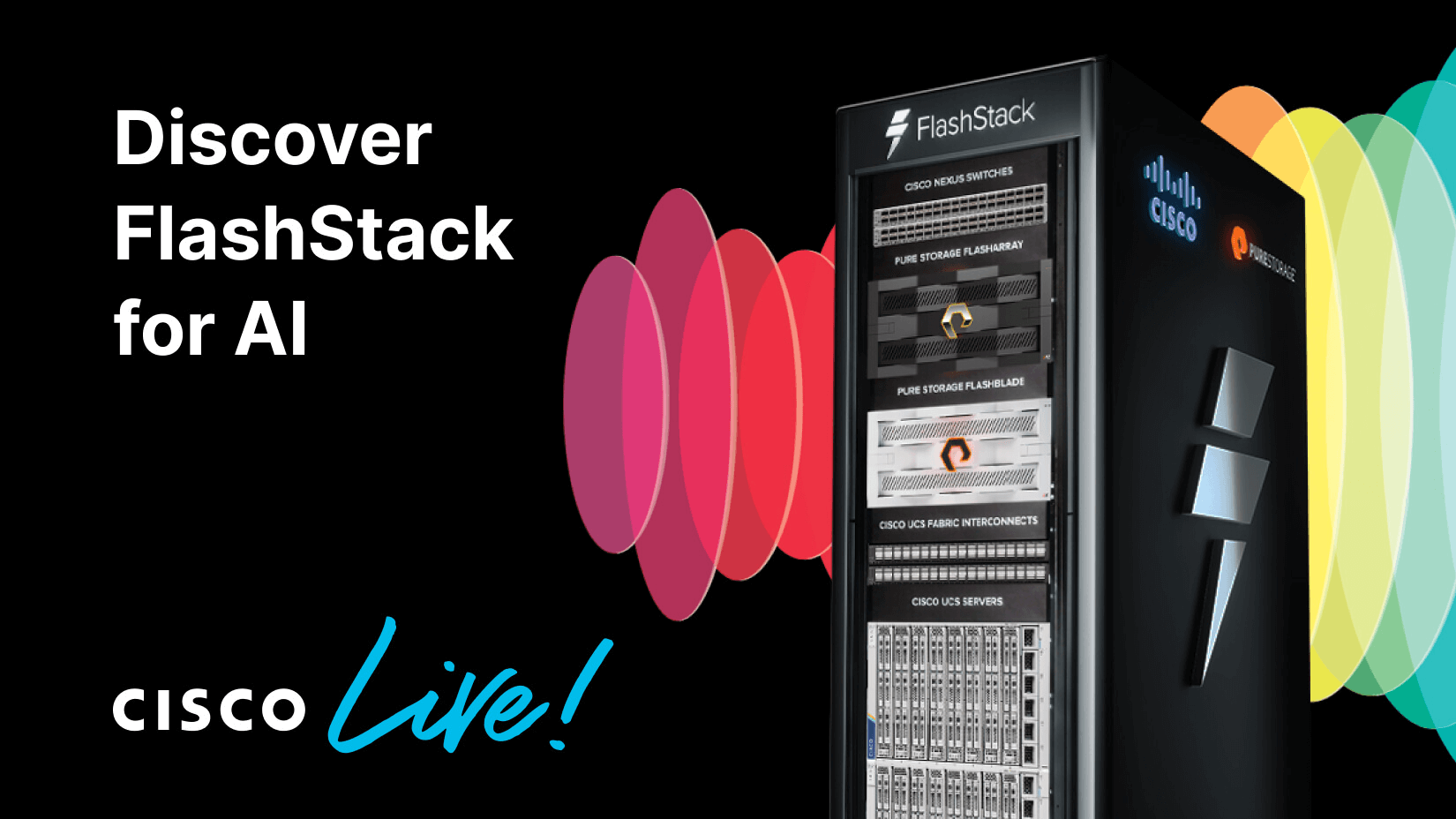


This year’s Cisco Live promises to be one of the most exciting Cisco Live events in many years. Cisco and Pure Storage, and our partners NVIDIA and Intel, will showcase how FlashStack® for AI helps AI teams innovate without boundaries and get on the fast track to AI success.
“AI is changing applications and infrastructure. With FlashStack for AI workloads, supported by the newly announced Cisco Validated Designs, IT organizations can deploy a validated architecture for AI workloads that reduces the design and investment risks when building a data, compute, and storage infrastructure for the AI data pipeline so data scientists stay focused on delivering AI solutions for better business outcomes.” –
Jeremy Foster, Sr. Vice President and General Manager, Cisco Compute
It’s no secret that one reason for Pure Storage’s phenomenal growth—significantly outpacing other storage vendors—is our leadership in AI storage. Wall Street analyst group the Hochfeld Independent Research Group, recently advised investors that “Pure Storage is the #1 choice for GenAI infrastructure.”
Pure Storage has already leveraged our consistent all-flash storage platform to help over a hundred customers, including some of the largest in the world, successfully navigate their AI journeys. With FlashStack as a foundation, UISA has fully automated its sugarcane production process using artificial intelligence (AI) and internet of things (IoT)—capturing and analyzing data from 850 equipment sensors across 222,000 acres of sugarcane fields.
“We trust the technology to work, and we have a solid partnership with Pure and Cisco, which means my team can focus on supporting our business.” –Rodrigo Gonҫalves, CIO, UISA
Join Pure Storage at Cisco Live 2024
June 2-6, 2024
Mandalay Bay Convention Center
Las Vegas, NV
Booth #4938

AI: New Possibilities and New Complexity
AI promises to fundamentally change the way we work and how organizations of all sizes execute their missions. Industries such as healthcare, finance, and manufacturing are already making AI an integral part of their operations. With the potential to generate valuable insights and attain new efficiencies, IT teams have been tasked to deploy infrastructure designed to harness the unique power of AI.
But building a full-stack AI infrastructure can be complex and time-consuming, requiring collaboration between IT architects, data center admins, data scientists, and DevOps professionals. New hardware requirements can be daunting to integrate and costly to deploy and manage. The large and diverse data sets required to train AI models can easily push the limits of traditional IT and storage architectures. Ensuring compatibility and seamless data exchange with existing IT systems and databases can be challenging. And AI often involves sensitive data, so security and regulatory compliance is crucial.
Therefore, it’s not surprising many organizations are feeling the strain that new AI models place on their IT infrastructure.
Meeting Modern AI Infrastructure Requirements
Companies remain optimistic about gains in productivity and competitiveness that will come from successful AI projects. But to get there, they must first deploy a reliable, efficient AI-ready infrastructure.
FlashStack for AI ticks all the right boxes.
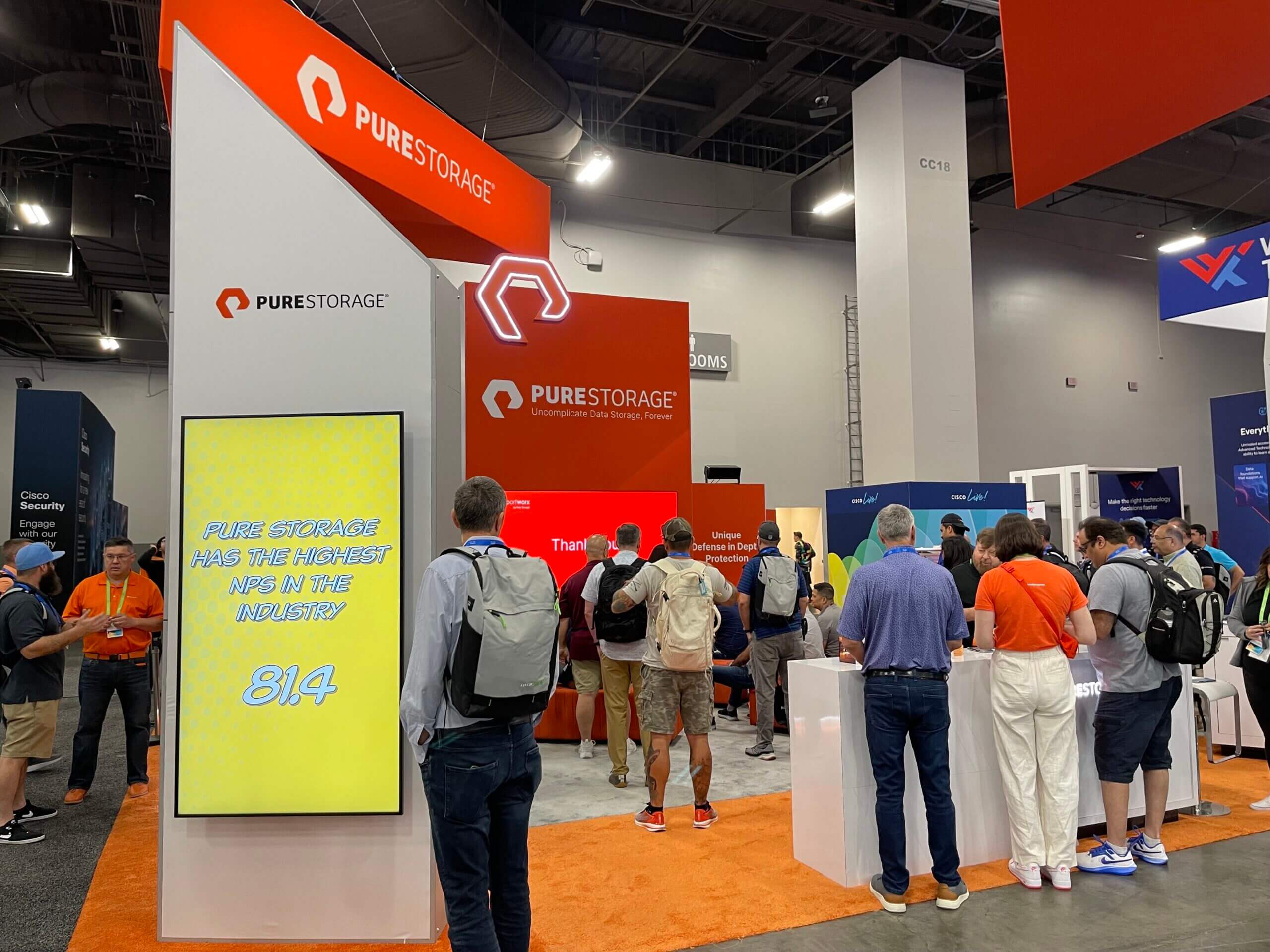
Pure Storage booth at Cisco Live 2014
With capacity on demand and integrated management across multi-cloud landscapes, FlashStack reduces the complexity associated with setting up an AI environment and simplifies expansion of your AI infrastructure as your needs grow. FlashStack’s high-density, high-performance architecture, designed to power demanding applications such as SAP and Epic, as well as data-heavy, unstructured and object workloads, is ideally suited to satisfy the need for efficient, risk-free AI deployments at any scale, giving AI administrators and data scientists a more efficient AI platform that helps generate insights faster:
- Performance: Performance is crucial for AI workloads’ complex computations and large data sets. FlashStack for AI leverages Pure Storage’s high-performance, low-latency, all-flash storage and up to 10:1 data compression to manage AI data quickly and efficiently. Industry-leading Cisco network and UCSTM compute, coupled with NVIDIA GPUs, complete the stack and ensure AI models can be trained and executed quickly and efficiently.
- Validated Designs: FlashStack for AI uses Cisco Validated Designs (CVDs) to provide detailed blueprints for foolproof deployment of AI platforms. CVDs can reduce deployment time by up to 60% and ensure installation is done correctly and reliably, reducing the risks often associated with running complex AI infrastructure.
- Scalability: Scalability is critical for AI solutions. The ability to selectively add more compute, storage, and networking resources as AI workloads grow is essential. FlashStack for AI is software-defined and discretely scalable, enabling organizations to expand their AI infrastructure as necessary without purchasing unneeded excess capacity, or worse, getting forced into forklift upgrades.
- Energy Savings: IT data centers consume vast amounts of energy, and new AI implementations only add to that climate strain. A recent survey found that 68% of companies said their internal targets for energy use are now under increased pressure because of how much power AI requires. FlashStack, however, was redesigned from the ground up to be the most sustainable and energy-efficient infrastructure available. Users have found that FlashStack typically reduces their data center footprint and energy usage by 85%.
- Automation: Pure1® software and Cisco Intersight intelligent management solutions help automate both complex and mundane tasks associated with AI infrastructure. Intersight provides single-pane-of-glass observability of your entire infrastructure stack, and along with Pure1, automates provisioning of needed capacity for more demanding AI projects.
- Simplified Hybrid Cloud Data Management: Managing AI data across on premises and multiple clouds can be complex. FlashStack for AI makes it easier to move, back up, and access data across hybrid cloud environments. Included unlimited snapshots and rapid recovery mean protecting and restoring valuable AI data in the cloud is as simple as it is in the physical data center.
- Security: Speaking of data protection, FlashStack for AI can leverage Pure Storage’s and Cisco’s “Defense in Depth” cybersecurity strategy. FlashStack infrastructure supports a layered approach to security including Cisco’s Security Cloud and XDR cybersecurity solutions for protection from the data center core to the network edge, integrated backup and recovery solutions from best-of-breed disaster recovery partners, and Pure Storage’s SafeMode™ immutable snapshots to ensure your AI data cannot be compromised.
- Container Management: AI deployments now often involve Kubernetes containerization. FlashStack for AI supports Portworx® by Pure Storage®, the leading container storage and data management platform. Portworx can be integrated into FlashStack infrastructure to easily manage AI containerized workloads.
- Subscriptions: Needed capacity for AI can be unpredictable, which makes aligning AI infrastructure costs to usage particularly challenging. FlashStack for AI supports Evergreen//One™ subscriptions, allowing organizations to pay for AI storage on a recurring basis rather than making a large upfront capital investment. Evergreen//One supports rapid data growth, so AI users are never caught without needed storage capacity, but never pay for more than they need.
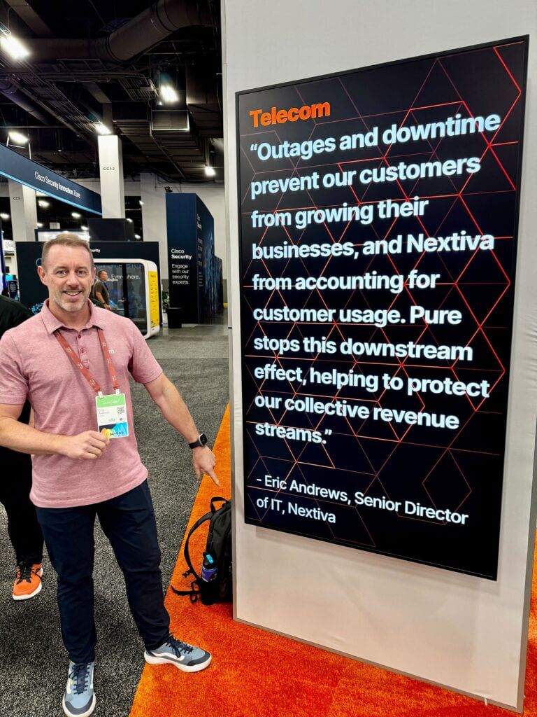
Pure Storage customer Eric Andrews points at his own quote at Cisco Live.
A Portfolio of AI Solutions for Any Scale
Data scientists and AI administrators can spend over 70% of their time on AI functional tasks such as data preparation, training, modeling, and tuning. The last thing they need to contend with is deploying and managing complex AI infrastructure.
To help simplify the process, Pure Storage offers a portfolio of integrated AI solutions including FlashStack for AI and AIRI, to validated NVIDIA OVX server and RAG reference architectures to make AI infrastructure faster to deploy for organizations of all sizes and AI maturity levels. Our AI platform is designed to help you navigate new AI application stacks and data pipelines while avoiding silos of infrastructure and operations.
Join us at Cisco Live 2024
Session 1: Free Your AI Teams to Innovate without Boundaries
- Wednesday June 5, 2024 at 2:00pm
- World of Solutions – Content Corner 1
- CNCDCN-2002
Session 2: Your Fastest Path to AI Success
- Wednesday June 5, 2024 at 3:00pm
- World of Solutions – Content Corner 2
- CNCDCN-1014
Written By:
Check All Your Boxes
Make your AI projects a success with full-stack AI infrastructure that addresses even the most challenging requirements.